[ad_1]
The examination of machining performance, cost, and environmental impact based on experimental data is the main focus of the section that follows. The experimental design matrix based on results obtained from the pilot trials is presented in Table 4.
Machining performance analysis
In this section, the impact of various machining variables, including I, SG, Pon, and DC, on MRR, Ra, EW, and EC during the machining process is discussed. Additionally, the study explores the effects of different electrode materials, specifically copper and brass, on these machining parameters. Similar parametric effects/trends have been observed for both copper and brass electrodes. Based on the observations in Fig. 2, it is evident that the average MRR experiences an increase from 1.78 to 2.67 mm3/min as I raised from 4 to 12 A for the copper electrode. At 4 A, discharge current intensity is insufficient to effectively remove a larger quantity of workpiece material. However, a substantial enhancement in MRR is observed when I increased to 12 A. This increase in MRR is mainly due to the production of intense spark discharges at the interface region. High intensity spark discharges melt and evaporate the workpiece material and eradicate more material from the work surface. The investigation revealed that widening SG from 6 to 12 mu leads to a decrease in MRR, dropping from 2.51 to 1.83 mm3/min. This reduction can be attributed to the increased distance between the electrode and the workpiece, which reduces the intensity of the spark discharge channel, resulting in a smaller volume of work material being removed. On the other hand, as shown in Fig. 2, an increase in Pon from 15 to 45 µs enhances MRR from 1.75 to 2.66 mm3/min. This improvement is attributed to the prolonged duration of spark discharges, leading to a more efficient removal of work material. When spark discharges are produced for a longer duration, more material is melted and evaporated from the work surface. An increase in DC from 75 to 85% improves MRR from 1.92 to 2.29 mm3/min. An increase in DC primarily results in an extension of Pon and a reduction in the Poff. At higher values of DC, Pon is higher enough to melt more workpiece material; however, the Poff is relatively shorter and remains inadequate for removing the melted material by flushing. For this reason, the material removal rate increases by increasing DC, but this increment is not significant compared to other machining variables. A comparative analysis of electrode material shows that copper electrode offer higher MRR (2.67 mm3/min) than brass electrode (1.64 mm3/min). The higher MRR exhibited by the copper electrode can be primarily attributed to its superior electrical conductivity, which enables a greater supply of electric current to the machining zone. In contrast, the brass electrode possesses relatively lower electrical conductivity, resulting in inadequate MRR during machining. Moreover, copper has a significantly higher thermal conductivity (401 Wm-1 K-1) than brass (150 Wm-1 K-1), which means it can dissipate heat from the electric spark/plasma more efficiently. With brass, more heat energy builds up locally, whereas copper spreads it out, maintaining stronger spark intensities for longer durations. The sparking phenomenon for copper and brass electrode at specific time t depicts that copper removed more material than brass electrode due to intense sparking, as shown in Fig. 3.

Analysis of the mean effects of machining variables and electrode material on MRR.

Schematic illustration for the material removal process using (a) copper and (b) brass electrodes.
Figure 4 illustrates the impact of machining variables and electrode material on Ra. From the graph, similar patterns of the effects of machining variables have been seen for Ra. It can be observed that the increase in I from 4 to 12 A increases Ra from 4.62 to 6.34 µm while using the brass electrode. This phenomenon can be attributed to the rise in the intensity of spark energy with an increase in I. Intense and irregularly sized sparks irregularly remove work material, producing deep craters and contributing to the formation of valleys. Moreover, a large amount of the work material resolidifies from the molten pool on the work surface and generates irregular peaks. These nonuniform peaks and valleys result in increased Ra. It has been observed that Ra increased slightly from 5.11 to 5.26 µm when SG was increased from 6 to 9 mu. Smaller spark gaps produce lower Ra due to the localized erosion, which is more consistent and controlled. There are fewer chances of uneven sparking and melting/vaporization at the edges of craters formed on the machined surface. Further increase in SG (to 12 mu) raises Ra significantly (up to 6.06 µm). Larger spark gaps, on the other hand, result in wider and deeper craters due to less focused spark energy over the gap distance. Figure 4 shows that a short Pon (15 µs) results in a relatively lower Ra of 4.58 µm, which is mainly due to less heat accumulation and reduced thermal energy transfer to the workpiece. Increase in Pon from 30 to 45 µs raises Ra 5.26 to 6.59 µm. A longer Pon provides a higher amount of discharge energy to the machining zone, leading to increased melting and vaporization of the work material. As a consequence, a significant amount of material from the molten pool solidifies and accumulates on the work surface, ultimately resulting in an elevated level of Ra.

Analysis of the mean effects of machining variables and electrode material on Ra.
Like other machining variables, DC also has a direct relation with Ra. Increasing DC from 75 to 85% raises Ra from 5.0 to 5.87 µm. A lower DC (short Pon and long Poff) allows more time for the melted material to flush away before the next spark, leading to a smooth and clean machined surface. Higher duty cycles concentrate more energy in a smaller area, which generates excessive heat and causes non-uniform melting and evaporation. This produces uneven layers of resolidified material with deeper and narrower craters on the work surface, leading to a rougher surface texture than lower duty cycles. A comparative analysis reveals that, when utilizing the specified machining variable settings during EDM of SS310, the copper electrode provides a comparatively superior surface finish (3.36 µm) compared to the brass electrode (4.58 µm). The enhanced surface smoothness of the workpiece can be attributed to the higher electrical and thermal conductivity of copper in comparison to the brass electrode. These enhanced conductive properties facilitate the generation of stable and controlled spark discharges, leading to a uniform dispersion of discharge energy, which ultimately results in a better surface finish. Conversely, brass has a lesser electrical conductivity, implying that less energy is transmitted to the plasma channel when electrical discharge machining is performed. Moreover, brass has a lower thermal conductivity, leading to a greater heat build-up in the plasma channel. Instead of a concentrated localization, this causes a less even dispersion of spark discharges across the machined surface. Consequently, the brass electrodeâs low thermal and electrical conductivities cause ineffective and erratic sparking as well as comparatively uneven craters and cavities on the machined surface. The surface texture produced by the copper electrode shows a relatively smooth surface with small and shallow craters, as shown in Fig. 5a. On the other hand, the brass electrode offers significantly higher peaks and deeper valleys on the machined surface of the workpiece, and the same phenomenon has been schematically illustrated in Fig. 5b. Owing to the lower melting, brass electrode face more wear during the machining which leads to inconsistent and irregular spark discharge. This results in uneven wear of brass electrode and ultimately transfers uneven material removal from the workpiece surface. Moreover, the lower electrical and thermal conductivities also result in uneven erosion of workpiece material due to erratic discharges.

Schematic illustration of the workpiece surfaces machined using (a) copper and (b) brass electrodes.
To gain insight into the surface attributes of the machining surfaces, scanning electron microscopy was performed at low, medium, and higher roughness values of machined surfaces for both electrodes, as shown in Fig. 6aâf. For this reason, the machined surfaces of Exp. No. 1, 4 and 7 have been chosen for morphological analysis. It can be seen that the low energy parameters (Iâ=â4 A, SGâ=â6 mu, Ponâ=â15 μs, DCâ=â75%) offered a quite smooth surface with few cavities and craters while using the copper electrode as shown in Fig. 6a. This better surface is primarily due to the moderate sparking which removes workpiece material gently. Similarly, the brass electrode also offers a better surface finish using the same machining variables; however, the machined surface produced with the copper electrode is finer and offers a smaller and limited number of craters than the brass electrode, as shown in Fig. 6d. Machined surfaces with cracks, wider and shallow cavities with tiny sized redeposited material and craters have been observed at Exp. No. 4 (Iâ=â8 A, SGâ=â6 mu, Ponâ=â30 μs, DCâ=â85%) using copper electrode (Fig. 6b). Figure 6e shows deeper cavities, cracks, globules and redeposited material on the machined surface generated by brass electrode using same machining variables. Higher energy parameters (Iâ=â12 A, SGâ=â6 mu, Ponâ=â45 μs, DCâ=â80%) result in a poor machined surface, as shown in Fig. 6c,f. However, a relatively better-machined surface with shallow cavities, globules and a few debris particles has been obtained with the copper electrode (Fig. 6c). In comparison with copper; the brass electrode produces large-sized globules, cracks, and numerous redeposited particulates can be visualized on the machined surface while using same machining variables (Fig. 6f).
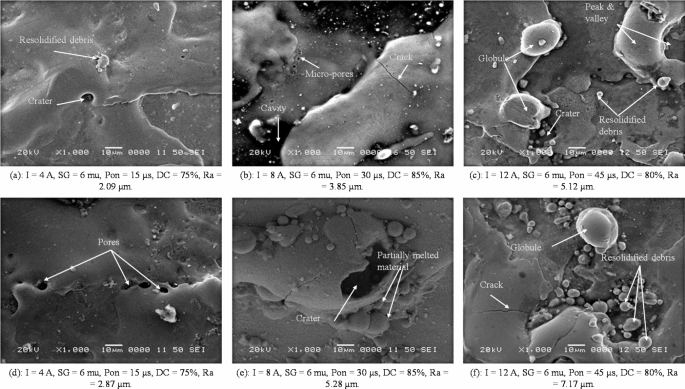
Scanning electron microscopic analysis of machined surfaces at Exp. No. 1, 4 and 7 using (aâc) copper and (dâf) brass electrodes.
Figure 7 depicts the contribution of different machining variables and electrode material on EW properties using copper and brass electrodes. It can be assessed that raising in I from 4 to 8 A increases EW from 0.334 to 0.394 g; however, this increment (0.521 g) is significant at 12 A using a brass electrode. The discharge current determines the amount of energy delivered during each discharge. As I increase, it generates greater thermal energy at the interface between the electrode and workpiece. This increased thermal energy not only facilitates the removal of workpiece material but also induces localized melting and vaporization of the electrode material, resulting in wear. Increasing SG from 6 to 12 mu reduces EW from 0.430 to 0.404 g, as shown in Fig. 7. SG affects the formation and collapse of the plasma channel during discharge. A larger SG requires a higher voltage to initiate the discharge, resulting in a limited and controlled discharge process. This controlled discharge can reduce the erosion of the electrode material, leading to reduced wear. Increasing Pon from 15 to 45 µs significantly raises the wear from 0.360 to 0.468 g of brass electrode. Pon directly impacts the thermal energy supplied to the electrode and workpiece interface during each discharge event. A longer Pon results in higher energy input, leading to increased localized heating and melting of the electrode material; hence, this increased thermal energy contributes to EW. DC also has a direct relationship with EW. Varying DC from 75 to 85% increases EW from 0.388 to 0.455 g (Fig. 7). DC directly affects the thermal energy transmitted to the electrode and workpiece interface. A higher DC (Pon is a greater proportion of the total cycle time) results in a longer duration of high-energy discharges and provides a short time for the electrode to cool down. This increased thermal energy input can lead to higher temperatures for a prolonged period of time and cause more significant localized heating, contributing to increased EW. A comparative analysis of EW shows that brass electrode yield more EW than copper electrode, as shown in Fig. 7. The melting point of the electrode material is one of the main reasons behind EW. The melting point of copper (1083 °C) is relatively higher than brass electrodes (940 °C). This means that copper electrode can withstand higher temperatures before melting or eroding. Brass electrods, on the other hand, have a lower melting point and can experience melting or erosion at lower temperatures. The lower melting point of brass can contribute to increased EW during EDM. The wear behavior of copper and brass electrodes is schematically illustrated in Fig. 8, which shows that the surface of brass electrode has higher erosion than copper.

Analysis of the mean effects of machining variables and electrode material on EW.

Schematic illustration of electrode wear for (a) copper and (b) brass electrodes.
The machining variables immensely influence EC in the EDM process, as workpiece material is removed by the electrical and thermal energies, which is a fundamental principle of EDM. An increase in I from 4 to 12 A leads to a notable escalation in EC, rising from 204.1 to 333.9 kJ when using the brass electrode, as depicted in Fig. 9. The discharge current determines the amount of electrical energy delivered during each discharge event. Increasing the I give more energy to the workpiece, resulting in a higher EC for the material removal process. Varying SG from 6 to 12 mu lead to reduce the EC from 302 to 238.3 kJ. A larger SG necessitates a higher voltage to maintain a stable discharge. This higher SG results in a lower I for the same energy input parameters. Moreover, fewer discharges are happening per unit of time, reducing the overall EC. Pon also has a direct relation and increases EC from 221.6 to 306.6 kJ with the increase in Pon from 15 to 45 µs. Pon directly contributes to the amount of energy delivered to the workpiece and electrode interface during each discharge. A longer Pon means that the discharge energy is supplied for a prolonged period of time, resulting in a higher energy input. EC also rises from 238.3 to 285.3 kJ, with the increase in DC from 75 to 85%. DC determines the portion of the discharge cycle during which the discharge is active. A higher DC, where Pon has a greater proportion of the total cycle time, allows the supply of more energy input. This can result in higher EC as more energy is delivered to the workpiece during the active discharge period.

Analysis of the mean effects of machining variables and electrode material for EC.
Figure 9 depicts the significant difference in EC of both copper and brass electrodes. It has been observed that copper electrode offers less EC throughout the experiment (for a 1 mm depth of cut) than brass electrode. Compared with the brass electrode, copper allows an efficient energy supply during the discharge process due to its higher electrical conductivity. As a result, using copper electrode can lead to lower EC as more electrical energy is effectively utilized for material removal. In contrast, brass has lower electrical conductivity, which leads to higher resistance to I flow. This increased resistance results in higher EC for the same machining conditions and parameters than copper electrode. Moreover, brass has lower thermal conductivity compared to copper, which might lead to increased EC, as the heat generated during the EDM process may not dissipate as effectively as it would with a copper electrode.
Machining cost assessment
Machining cost analysis helps in estimating the cost of producing a machined part or component. Analyzing the machining costs allows manufacturers to identify areas where costs can be optimized and reduced. In this regard, optimization of the machining variables is crucial in order to minimize the cost. Therefore, this section analyzes the effects of different machining variables on energy cost, electrode cost, dielectric cost, labor cost and machine depreciation cost using both copper and brass electrodes. Energy cost refers to the cost incurred due to the energy consumed during the material erosion process. Electrode cost is the cost of the electrode material eroded during the machining; moreover, it also includes the cost of electrode material removed to obtain the fresh face of the electrode for the next machining experiment. After each experiment, 2 mm (across the length) of the electrode material was removed/machined to acquire a fresh face surface. The cost of dielectric is calculated by measuring the cost of the volume of the dielectric fluid consumed by evaporation during each experiment. Besides this, labor and machine depreciation costs are also analyzed with respect to the selected machining variables. Labor and machine depreciation costs are computed with respect to the machining time of each experiment. Unit values of different cost factors for the calculation of energy cost, electrode cost and dielectric consumption cost are provided in Table 5. Using experimental data and unit costs of different factors, the energy cost, electrode cost, dielectric consumption, labor cost and machine depreciation cost are computed.
By observing Fig. 10, it becomes evident that there is a direct correlation between energy cost and EC. An increase in I, Pon, and DC leads to higher machining costs due to the corresponding rise in EC. However, the increase in SG reduces EC, hence resulting in low energy costs. The analysis of mean values of costs depicts that the energy cost of brass electrode is relatively higher (2.83 PKR) than that of copper electrode (2.02 PKR). The main factor contributing to the higher energy cost is the inefficient energy supply, primarily resulting from brassâs lower electrical and thermal conductivity compared to copper electrodes. Additionally, the machining variables have an impact on EW due to variations in the amount of energy delivered to the machining zone. Higher levels of I, Pon, and DC, along with a lower SG, lead to an intensified energy supply that causes melting and evaporation of the electrode material from the machining zone. For this reason, high electrode cost has been observed on higher energy parameters than low energy parameters, as shown in Fig. 11. Owing to the variation in the melting point and electrical and thermal characteristics of copper and brass electrodes, the EW behaviour of both electrodes is significantly different from each other. Brass has a low melting point and electrical and thermal characteristics; therefore, higher EW has been observed. However, contradictory results have been observed in the case of electrode cost. The copper electrode yields a higher electrode cost of 5.54 PKR than the brass electrode (3.66 PKR), as shown in Fig. 11. It can also be seen that the machining variables also affect the dielectric consumption (Fig. 12). As discussed, higher levels of I, Pon, and DC, and lower level of SG supply intense energy to the machining zone. This intense energy also evaporates the dielectric fluid during sparking. Therefore, the evaporation of the dielectric fluid incurs the dielectric cost. The comparative analysis revealed that the usage of brass electrode resulted in significantly lower dielectric cost (22.28 PKR) than copper (5.203 PKR) as depicted in Fig. 12. It is primarily due to the supply of lower energy (in the case of brass electrode) to the machining zone, which remains inadequate to evaporate dielectric fluid. Due to less evaporation of the dielectric fluid, the cost of dielectric consumption remains lower than that of the copper electrode.

Analysis of the mean effects of machining variables on EC and energy consumption cost.

Analysis of the mean effects of machining variables on electrode material removed and electrode cost.

Analysis of the mean effects of machining variables on dielectric consumption and dielectric cost.
A distinct behavior of the labor cost and machine depreciation cost with respect to the selected machining variables has been observed in Fig. 13. It can be seen that the increase in I, Pon and DC speed up the material removal process due to the intensive energy supplied to the machining zone. This intensive energy minimizes the overall machining time and ultimately reduces the labor hours and machine operating time; hence, labor cost and machine depreciation costs are decreased. However, the increase in SG supplies less energy to the electrode and workpiece interface region; therefore, machining time increases to remove the specific amount of material. This increased machining time also raises the labor and machine depreciation costs. Comparative analysis of the electrode materials depicts that copper electrode reduces the labor cost (80.12 PKR) and machine depreciation cost (99.3 PKR) than brass electrode (129.4 and 160.4 PKR, respectively), as shown in Fig. 13. This decrease in cost is mainly attributed to the reduction in machining time owing to the better supply of energy to the machining zone. The improved supply of energy is mainly due to the better electrical and thermal conductivity of copper compared to brass electrode.

Analysis of the mean effects of machining variables on labor and machine depreciation costs.
Environmental impact analysis
Machining processes consume a significant amount of energy, which, in turn, supplies a considerable amount of carbon footprints for the environment34. In order to evaluate the carbon emissions generated from EC, it is necessary to calculate the carbon emission factor. For this reason, the power production in Pakistan comes from different sources (including hydro, natural gas, coal, furnace oil, nuclear and renewables), and their contributions to the total power production are provided in Table 6. The standard values of carbon emissions of each source are considered to compute the carbon emission factor of energy production in Pakistan. The carbon emission factor from Pakistanâs power production has been determined as 0.242 kgCO2 eq./kWh, and it was used to assess the carbon emissions resulting from the EC during each experiment. Moreover, dielectric fluid and EW consumption also result in an environmental burden. Therefore, the volume of the dielectric fluid was measured after each experiment, and the carbon emissions from the consumption/evaporation of dielectric fluid were determined using the carbon emission factor of the kerosene oil, as shown in Table 7. Carbon emissions of each experiment for both copper and brass electrodes have been computed by considering EW and material removed/machined (2 mm across the length) to attain the fresh face for each experiment. The carbon emission factors for copper and brass electrodes are provided in Table 7.
A mean effects analysis was conducted to examine the impact of various machining variables on carbon emissions resulting from EC. Figure 14 illustrates that increasing the levels of I, Pon, and DC leads to higher carbon emissions from EC. This is primarily due to increased electrical energy consumption at higher energy levels than the above-mentioned parameters. However, the increase in SG decreases the carbon emissions due to reduced energy supply to the machining zone. A relative analysis of electrode materials shows that carbon emissions from EC due to the usage of the brass electrode (13.72 g CO2) are higher than that of the copper electrode (9.80 g CO2), as shown in Fig. 14. Higher electrical and thermal conductivity of copper enables more energy-efficient sparking than that of brass. This directly translates to lower electricity consumption and reduced carbon footprint from EC. Figure 15 depicts the mean effects of the machining variables on the carbon emissions produced from the dielectric fluid (kerosene oil) consumption. Another observation reveals that the heightened levels of I, Pon, and DC result in the delivery of intense energy to the machining zone, leading to the evaporation of dielectric fluid. This evaporation process directly contributes to carbon emissions being released into the environment. Conversely, an increase in SG provides a lesser amount of energy to the machining zone, resulting in the evaporation of a lower volume of dielectric fluid and ultimately reducing carbon emissions. A comparative analysis of electrode materials demonstrates that the brass electrode results in lower carbon emissions (32.33 g CO2) due to the consumption of dielectric fluid as compared to the copper electrode (54.58 g CO2), as depicted in Fig. 15. It is because of higher electrical and thermal conductivities of copper than brass electrode which cause intense sparking and generate higher temperatures at the machining zone. This higher temperature vaporizes the dielectric fluid from the interface region; hence, carbon emissions due to dielectric fluid consumption are higher in the case of copper electrode.

Analysis of the mean effects of machining variables on carbon emissions from EC.

Analysis of the mean effects of machining variables on carbon emissions from dielectric consumption.
Figure 16 illustrates the impact of various machining variables on carbon emissions resulting from electrode erosion. The analysis reveals that an increase in I, Pon, and DC leads to an intensified supply of energy to the machining zone, resulting in greater erosion of the electrode material and higher carbon emissions. Conversely, an increase in SG reduces the supply of discharge energy, leading to a lesser amount of electrode material being melted and evaporated, ultimately resulting in lower carbon emissions. Analysis of carbon emissions due to electrode consumption in Fig. 16 describes a distinct behavior compared to Fig. 7 (showing the mean effects of EW), providing a comparative analysis of EW. As mentioned earlier, the wear of the brass electrode was found to be higher than that of the copper electrode. Consequently, it can be inferred that the carbon emissions associated with the brass electrode would be higher compared to the copper electrode. However, the analysis provides the carbon emissions of EWâ+â2 mm length of electrode material removed (to obtain the fresh electrode surface for the next experiment). As the production of 1 kg of copper releases more carbon emissions than 1 kg of brass, therefore, a distinctive behavior of the carbon emissions has been observed in Fig. 16. This is mainly due to the 2 mm length of electrode material removal for each experiment, which overcomes the effects of EW, and higher carbon emissions are obtained in the case of copper electrodes (5.07 g CO2). This is primarily due to the immense carbon emissions produced during the production of copper and brass, however, brass has a significant proportion (35 wt%) of zinc, which reduces the overall carbon footprints of brass production (Table 7).

Analysis of the mean effects of machining variables on carbon emissions from electrode erosion.